
As mentioned in Chapter 1, Googling found me an article for RIT. The article was sritten by John Grebenkemper, WA6BVA, and appeared in the July 1975 QST, simply titled RIT for the HW-7.
Here's how I think RIT is created in John's HW7: The battery supply feeding the VFO is stabilized using a Zener diode to bias a NPN switching transistor to be a voltage regulator. Now that the VFOs FET is stable then the FETs Biasing can be altered to predictably change the frequency. Resistors in series with the cold side of RFC-1 (Q2 Source to GND) alter the bias to change the frequency. On 40 meters additional biasing is needed so an extra resistor is added between the Drain and cold side of RFC-1 (via extra contacts in the 40M bandswitch)...Please read the article for more in depth info and to check my accuracy.
I did the mod as John's QST article prescribed. It worked very well... but I didn't like the fact that the range of the RIT adj pot increased as the frequency increased. Example: On 40M a 1.4 KHz shift occurs, On 20M there's a 2.4 KHz shift, and 15M results in a 3.4 KHz shift. It works and the VFO is amazingly almost drift free...but there's too much RIT range for my liking. Using the RIT Pot for fine tuning was not all that fine especially on 20M and 15M. Tic marks on the front panel for each band are needed.
Here's how I think RIT is created in kr7w's HW7: Since transistors Q103 and Q102 switch in/out the RIT adj pot while on receive... and on 40 meters a spare set of contacts from the band switch are used to add the additional 3.9K biasing resistor... I axed myself, "Can I use additional contacts in the 20 and 15M bandswitch to operate transistors to add the appropriate resistance for preset RIT of 700 Hz for CW offset as well as a RIT adj pot?" After some pondering... that's what I ended up doing.
But first, do this for me: If you are interested in modifying your HW7 like I did or want to use the concept for another project... then please read John's QST article and get a more techy description of what he did.
 |
| Comments below refer to this schematic from the QST Article. |
VFO Voltage Reguator: The Q104 voltage regulator BJT takes the place of the original R23- 100 ohm resistor. Using the holes in the PCB from R23 and a couple of additional drilled holes- I added Q104,the 11V Zener diode, and 4.7K. I didn't have the exact Zener, so I soldered two 5 volt Zeners in series. [Sidenote: according to my super Geeky engineer ham radio friend, Bob... this type of voltage regulation is far superior to Linear regulators and/or Zener diodes by themselves]. The regulator output is the Zener value minus .7 volts from the voltage drop across the transistor, BTW.
I added transistor Q101 and R101 next to original RF Choke RFC1. I drilled holes in the PCB... but the VFO tuning capacitor must be removed to do this. (I will have, "If I was to do this differently- this is how I'd do it" thoughts at the end of this blog entry). A wire was run to the 12V Key Line (+12 volts applied when key is down) and to the RIT pot. C101 bypass cap was installed under the PCB in the area of RFC1.
The QST article shows a 3.9K ohm resistor-R104 being switched in when on 40M only. For an unknown reason to me now, I soldered this resistor in permanently. All 700 Hz offset resistor values were determined with the R104 in the circuit on each band.
 |
| This is my rendition (first hand drawn then annotated with Photoshop) of the RIT modification to my HW7. Circuit description follows... Note: Just like there are no A, B, or C ionospheric propogation layers... there is no Q102A- there used to be... but it was removed to lessen the complexity. |
Example of Operation: 40M RCV- When RIT pot is set in the center (~50 ohms) the bandswitch applies +12V (thru 10K) to the B of Q102B. This transistor conducts and GND appears on the Collector. This completes the path of 220 ohms in series with the RIT Pot which causes the VFO to shift its frequency ~700 Hz from the Transmit Frequency. Note: The 220 ohms was determined by trial and error using my Icom transceiver with my Fluke VOM. The procedure is described below.
40M XMiT: When the Key is down, Q103 conducts and grounds out the Vcc on the Collector. This causes Q102B to not conduct which opens up the RIT 100 ohm pot path. Also, with Key Down... Q101 conducts and GNDS its Collector which places the 120 Ohm resistor in place of the RIT pot resistance path which determines the XMIT frequency.
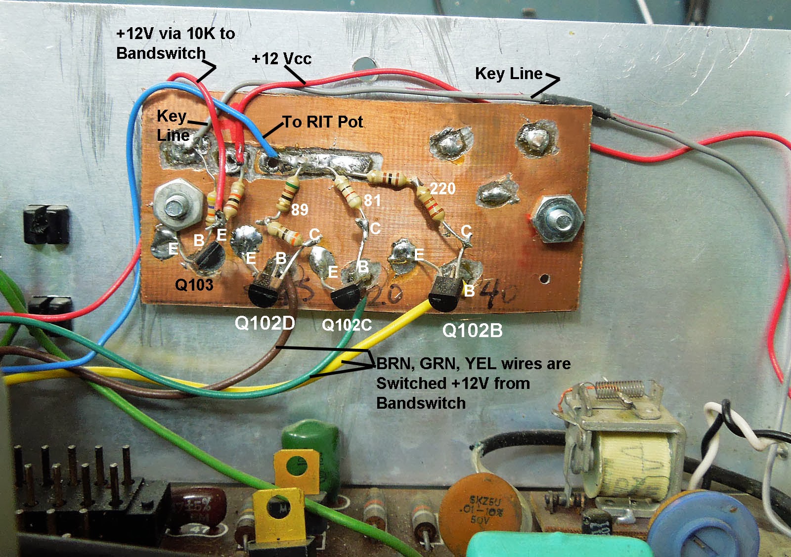 |
| This is the circuit board I fabricated to contain Qs102B-D and Q103. Construction is in the Manhattan and dead bug style. A hand held Dremmel tool with a conical shaped dentists grinding stone was used to route out some islands for wires and BJTs to be blobbed soldered to. Looks messy- but it works. Wires to/from the board route along the vertical sides of the chassis. No X-country wires. All transistors are BJT MPS2N2222 acting as switches. |
Regarding the RIT pot I installed... I lucked out and found an old junked out Cushman CE-3 service monitor at my radio club. I harvested a very nice 100 ohm pot with a long enough shaft to fit through of the two front panels of the HW7.
 |
| Here's a foto of the location of my RIT pot. Also seen is the bandswitch where I picked up spare contacts for the RIT/offset circuitry. |
 |
| Here's a foto of my HW7s inner front panel. Hole 1, 2, and the RIT pot hole were already drilled in the inner panel (but not the front panel) before I rescued this radio. The once pristine green front panel has been defaced with holes for the RIT control... and most recently holes 1 and 2 have been drilled in the front panel for push-button switches for the upcoming Freq-Mite and PK-4 Keyer controls. |
If I were to do this again:
>Even though Q101s functional position is where I put it- next to RFC1, under the VFO tuning capacitor... I would put it on the homebrew PCB. My reasoning is that since all wires are DC control (no RF signals) then having Q101 on the PCB would ease in trouble shooting and would lessen a couple of wires running along the chassis walls.
>I will order some small 500 ohm Ten Turn pots to adjust the offset resistor value for each band. The pots should be easy enough to solder to the PCB with the transistors.
700 Hz Offset test procedure:
Note: When the HW7 is transmitting the RIT Pot has no affect on the output frequency.
Pick a band and transmit a carrier with the HW7 into a dummy load. Tune in the HW7 with a good HFT (HF transceiver). Zero beat the HW7s signal in the HFT or make sure it is tuned in properly for a 700 Hz offset. Do not touch the HW7s VFO dial from this point on.
Connect the HFT to a dummy load and transmit a CW carrier on the exact same frequency that the HW7 was received. On the HW7, make sure the RIT Pot is in the middle of its range. Do not touch the HW7s VFO dial to tune in the HFTs signal.
Measure the beat tone from the HW7s Audio out with an audio frequency meter- Fluke VOM or equivilent device. This is the HW7s offset frequency. It should be 700 Hz or the frequency you like to listen to CW with. Adjust the resistor value in series with the RIT pot for the band you are operating on... until 700 Hz is obtained.
End of procedure.
I was working on adding the Freq-Mite and PK-4 keyer to the HW7... and in the process of not treating sensitive semiconductors properly... I somehow blew out the PIC chip in my PK-4 keyer. I ordered two new chips plus a complete unit with circuit board to install in my HW8 someday.
Still to come:
> Progress on the 'new ears-best it can be SA602A Mixer direct conversion receiver.
> PK-4 Keyer for paddles + SK + sidetone.
> Freq-Mite frequency Morse Code output frequency counter + its sidetone.
Sidetone is a big deal to me. I do not like to listen to my Morse sending via square wave audio tones, like the HW7, RockMite, PFR-3, NE555 Astable oscillator and PIC based audio generators. I've been experimenting on how to filter out the squares in square waves for more pleasant CW listening.
End of this Blogger Entry. Please email me for info or if you have some ideas to share regarding this project. 71r5, Rich KR7W... -30-
No comments:
Post a Comment
Note: Only a member of this blog may post a comment.