
This article was originally written in 2013. For an unknown reason- Google's Blogspot had denied access. Now, The New and Improved Ver 2 has been edited to remove the 'fluff' for clarity and easier to access.
My intended purpose for this higher efficiency, more gain that a 14-inch rubber duckie 2 Meter portable antenna was to slip it into an outside pocket of my hiking pack to transmit my APRS Position whilst enroute to Summits On The Air Peaks. Once I reached the peak- then the antenna would be used for 146.52 FM contacts.
Before I retired- I worked as a 2Way Radio Technician. One of the common base station antennas I encountered was the Coaxial Dipole... sometimes known as a Sleeve Dipole... where a metal sleeve on the lower side of the antenna acted as the counterpoise. The coax cable feed line below the sleeve didn't affect the tuning or performance. Motorola spec sheets say the sleeve dipole is the same gain and performance as a J-pole, a Roll-up Slim Jim- but without the extra length of the 19-inch tuning stub.

Above drawing: The location where the coax shield ends, and the top radiator (the whip) begins is the dipole's FEED POINT, the center of the dipole. One of the 1/4 Wavelength poles is the top section whip. The opposite pole is the coax's shield from the feed point to the beginning of the 7-8 turns of coax. The coil or turns of coax act as a Radio Frequency Choke. The purpose of the RF Choke is to stop RF from traveling any further down the coax feed line to the radio. The RF energy stops 18 in from the feed point- which is the correct length for 1/4 Wavelength 2 Meter radiator.
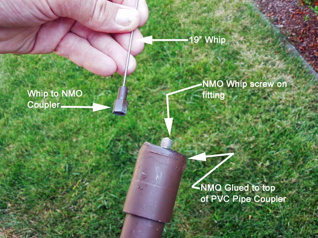
The main support or handle of this antenna is 3/4" PVC Irrigation pipe which houses the coax cable lower pole. Sked 20 or 40 will work. A mobile whip antenna was added as the top pole- so to survive an occasional tree branch collision when hiking with the antenna in my pack.
Finished antenna shown below:


NMOQ (quarter wave) has no loading coil inside.

After cutting the cap it should look something like above.
When I place the antenna in a pocket of my pack- the whip extends about 18" above my head.
I sometimes use another 18" piece of PVC pipe with a coupler as an extension for this antenna to elevate it higher when I think I am in a Sketchy APRS area. The extension makes it easy to jam into cracks or a rock pile on a summit. It also makes it easier to get bonked off the trail by hitting that low hanging branch. I have used electrical tape to secure it to my trekking pole handle stabbed into the dirt.

The piece of Perf Board supports the coax inside of the PVC pipe and makes the connection to the hacked NMO cap. Plywood, Plexiglass, or other non-conductive material can sub for Perf Board.

A= Heat shrink tubing is placed over the coax center insulation because when soldering the center conductor wire to the larger copper wire... the heat will melt the coax insulation. The heat shrink keeps it from melting out of place.
B= Solder the coax center conductor to the NMO connection. Once soldered- use wet paper towel to absorb excess heat.
C= Epoxy or hot glue could be added at this joint for rigidity.
B= Solder the coax center conductor to the NMO connection. Once soldered- use wet paper towel to absorb excess heat.
C= Epoxy or hot glue could be added at this joint for rigidity.


The 3-inch slot cut into the PVC pipe provides adjustment of the location of where the beginning of the coax RF Choke coil starts. If the antenna needs to be longer then move the coil further down- this makes the length of coax inside of the pipe longer.
The RF Choke coil can be temporarily secured in place with electrical tape while SWR testing takes place. Once the coax coil position is found- a couple of wraps with quality electric tape will hold it in place for years to come.
A standard 1/4 VHF quarter wave mobile whip antenna is used as the upper pole of the dipole.

A standard 1/4 VHF quarter wave mobile whip antenna is used as the upper pole of the dipole.
ADDITIONAL INFO Section...
I built another version of this antenna called the Lazy Pole- which uses a 3/4-inch wooden dowel for the support. The article for it is at:
Page 24
[ www.w7dk.org / Newsletters / April 2020 / Page 24
A 15 ft long RG-174 coax jumper with SMA (for Japanese handy talkies) and a Reverse SMA (for most Chinese handy talkies) coax connectors on each end can be purchased here:
Superbat RF coaxial SMA Male to SMA Female Bulkhead RG174 15ft Cable + 3pcs RF Coax SMA Adapter Kit for SDR Equipment Antenna Ham Radio,3G 4G LTE Antenna,ADS-B,GPS and etc : Electronics
The Flowerpot antenna is another version of the Coax Dipole Antena:

Note: if the link does not work- please cut n paste it into your search engine.
Simply cut off the coax connector that does not match your radio.
Above I mention 'Quality Electrical Tape' my fav is Scotch 33, found at Home Depot.
The Flowerpot antenna is another version of the Coax Dipole Antena:
Again, if the link does not work- cut n paste it into your search engine.
You'll need a metric to Imperial length converter. There's an app for that.
The effectiveness of the Coaxial Dipole (named "The Home Brew Dipole") was tested as compared to other antennas typically used on a Handy Talkie. See:
bark_2018_10.pdf (w7dk.org) Cut n Paste if necessary.
Scroll to Page 6
[ w7dk.org / Newsletters / Oct 2018 / Page 6 ]
End of this blog entry. Best Regards, Rich KR7W
Email me if you have questions. QRZ lookup will find me.
Photo Below: Summits On The Air expedition. Coaxial Dipole is being held up by the brush. KR7W has QSO with a ham approx. 50 miles away- line of sight- 5 watts Kenwood Handy Talkie.
No comments:
Post a Comment
Note: Only a member of this blog may post a comment.